How to Make Microfluidic Connections
What is a Microfluidic Fitting?Fittings typically comprise of a nut and a ferrule. The nut provides the driving force which compresses the ferrule around the tube which both holds the tube in place and makes a leak-tight connection.
Determining which nut and ferrule are best for your application depends on the following.
|
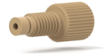
In addition to the above two-piece nut and ferrule fittings, there are also one-piece fittings where the nut and ferrule have been combined, offering the user convenience and ease-of-use.
|
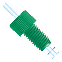
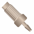
Microfluidics most typically comprises low-pressure applications. Low pressure fitting types include flanged and flangeless. With flanged fittings the flow path tubing is flared out at the end, and the supporting fitting presses the tubing flare against the bottom of the receiving port. Although flanged fittings are still used, there has been a migration away from this fitting type toward flangeless fittings which are commonly referred to as flat bottom fittings. The ferrules used with this flangeless fitting type have their taper facing toward the nut and away from the flat bottom receiving port. The threaded barrel of the nut will often feature an internally tapered surface, designed to interface with the tapered nose of the ferrule to aid the frusto-conical seal around the tubing wall. The ferrule should have a narrower angle than the receiving port so when the fitting is tightened, the ferrule conforms to the port’s angle, compressing both around the tubing wall and against the internal surface of the receiving port. These low-pressure connections require only finger-tightening to make leak-tight seals. NO TOOLS NEEDED! If tools are used to tighten, damage to the fitting, receiving port and tubing end can result.
Specialty Fittings
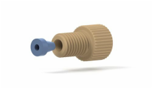
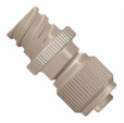
Barbs: Barbed connectors are compatible with only soft tubing and low pressure applications. A connection is made by forcing the soft tubing to expand over a barbed nose. The barbs on the connector grip the tubing, keeping it in place.
|
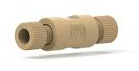
Adapters / Unions: Adapters connect two different types of thread/port configurations while unions have the same thread/port configuration on both sides. But unions can still be used to connect tubing with different outer diameters by using appropriate fitting types. For example a union for ¼-28 flat bottom fittings could connect 1/16-inch outer diameter tubing on one side to 1/32-inch outer diameter tubing on the other.
|
Luers: Luer adapters allow for microfluidic researchers to make quick connections to syringes.
|
TubingThere are several important considerations when choosing tubing.
|
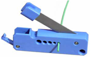
A cutting tool provides straight,
clean tubing end cleavages. 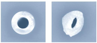
An example of a good cut (left)
and a poor cut (right). |
What is Dead-Volume and Why Should it Be Avoided?Dead-volume refers to the empty, solvent-accessible pockets that are unintended portions of the flow path. Dead-volume is created when fittings seat improperly into receiving ports. Dead-volume is always undesirable in any fluidic application as it can contribute to diffusion effects and adsorptive loss due to the increased surface area. However in microfluidics, dead-volume poses an even more detrimental threat as it creates regions where air bubbles or compressible gas can trap. These air pockets can lead to bubble release, as well as flow pulsing due to the presence of compressible gas in the flow path. Furthermore, when working with live cells, if the cells are exposed to air, cell death will result. Consequently special care needs to be taken to eliminate dead-volume in microfluidic systems.
|
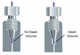
Dead-volume occurs when unintentional, solvent-accessible pockets are in the flow path. Here connections with no dead-volume (left) and with dead-volume (right) are shown. Dead-volume should be avoided.
|
A Review of Current Connection Approaches to Microchips
|

|
- A threaded port is glued to the substrate surface, such as with IDEX NanoPorts™. If done properly, this approach does isolate the adhesive from the liquid, by using an o-ring to make the actual seal to the substrate surface. However the presence of this o-ring creates a large dead volume gap in the process. This dead volume gap is unlikely to fill completely with liquid, creating a pocket of air in the system. The presence of such an air pocket could cause the system integrity to be compromised. It is possible that bubbles would be released from the air pocket into the system. It is also possible that the compressive gas in the system’s flow path could create uncontrollable fluid pulsing. If live cells were used, and they came in contact with the air pocket, it is possible that cell death would result. In addition to dead volume introduction, other drawbacks of the technique include its large size which eliminates the possibility of tight port densities, only one-time use, and significant cure wait-times.
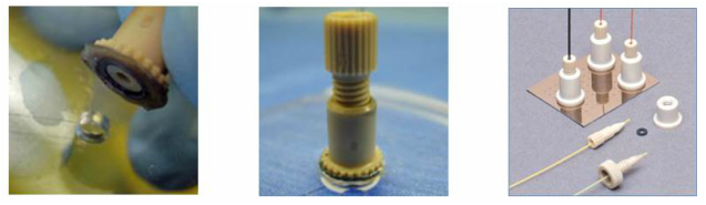
Examples of fittings glued to microdevice substrates are provided. The o-ring alignment is critical when a
fitting is being adhered to a port (left). Once adhered, the fitting is permanent and cannot be removed,
even if the connection does not prove to be leak-tight.
fitting is being adhered to a port (left). Once adhered, the fitting is permanent and cannot be removed,
even if the connection does not prove to be leak-tight.
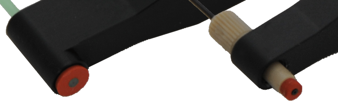
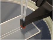
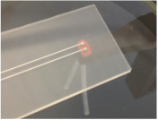
Images of CorSolutions connectors are shown. A single connector for 1/16-inch tubing and a single connector for 1/32-inch tubing (right) is shown. The gaskets, in red, are reusable. An example of a connector sealing to two ports is shown in the middle image. The underside view of this of dual connector is also shown (right).
|
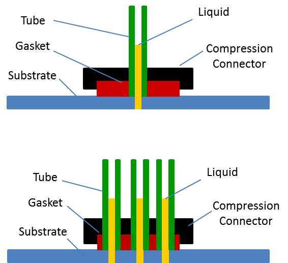
Cartoon cross-section of CorSolutions microfluidic connectors. A connector simultaneously compression seals a gasket around a tube and to a substrate. The approach is non-permanent, requires no adhesive, is zero dead-volume, and allows for one (top) or more connections (bottom) to ports in close proximity.
|